5.10 - Quick Reference
Module: Recovery Recycling Reclaiming Evacuation and Dehydration
Covers: Sections 5.1–5.9
Regulatory verification date: August 9, 2026
Use: Rapid review before the Module 5 practice questions and later Core/Universal certification review
1. Recover Recycle and Reclaim
The Three Rs
| Term | Quick Meaning | Main Result |
|---|---|---|
| Recover | Remove refrigerant from an appliance and store it in an external container | Refrigerant is captured; no cleaning or purity verification is necessarily performed |
| Recycle | Extract and clean refrigerant, commonly by oil separation and filtration | Refrigerant may be suitable for reuse within equipment of the same owner |
| Reclaim | Reprocess used refrigerant to the applicable purity specifications and verify purity analytically | Refrigerant meets the applicable reclamation standard |
Three-Word Memory Aid
RECOVER → REMOVE
RECYCLE → CLEAN
RECLAIM → VERIFY
Ownership Rule
Same owner
→ recovered and/or recycled refrigerant may be reused
→ reclamation is not required solely because of that reuse
New owner
→ used refrigerant generally must be reclaimed
→ before sale or transfer for use as refrigerant
High-Priority Reminders
- Recovery does not automatically clean refrigerant.
- Recycling does not automatically make refrigerant reclaimed.
- Reclamation requires:
- Applicable purity specifications.
- Analytical verification.
- An EPA-certified refrigerant reclaimer.
- A field refrigerant identifier does not prove reclamation purity.
- Same-owner reuse does not make mixed or contaminated refrigerant technically acceptable.
- For current Section 608 regulatory purposes, the reclamation purity framework incorporated into the rule is based on AHRI Standard 700-2016.
2. Recovery Equipment Categories
System-Dependent Versus Self-Contained
| Equipment Category | How Refrigerant Is Moved | Common Study Term |
|---|---|---|
| System-dependent | Requires assistance from appliance components, refrigerant pressure, or another appliance condition | Passive |
| Self-contained | Removes refrigerant without appliance-component assistance | Active |
Memory Aid
SYSTEM-DEPENDENT
→ Appliance helps
SELF-CONTAINED
→ Recovery machine can work independently
Important Conditions
- A functional appliance compressor may be part of a system-dependent recovery method.
- Refrigerant pressure or pressure difference may also drive system-dependent recovery.
- A self-contained recovery machine commonly has its own refrigerant-moving mechanism.
- A failed appliance compressor can prevent a method that depends on that compressor.
- A recovery cylinder stores refrigerant; it is not itself the recovery machine.
- A vacuum pump is not a general-purpose refrigerant recovery machine.
15-lb Limitation
Appliance full charge > 15 lb
→ ordinary system-dependent recovery equipment prohibited
Exception:
System-dependent equipment permanently attached
as an appliance pump-out unit
→ specific exception may apply
The 15-lb threshold is based on the appliance full charge, not the amount of refrigerant remaining after a leak.
3. Recovery Equipment Certification and Service Access
Technician Versus Equipment Certification
Technician certification
→ person
Recovery-equipment certification
→ equipment model
Approved Testing Organizations
EPA currently identifies:
- AHRI
- UL
as approved recovery-equipment testing organizations.
Important Equipment Dates
| Date | Quick Significance |
|---|---|
| November 15, 1993 | Major boundary for modern third-party recovery-equipment certification and several recovery requirements |
| September 22, 2003 | Appendix B1 equipment period changes to Appendix B2 |
| January 1, 2017 | Appendix B3/B4 framework applies to current-generation equipment as described in Section 5.3 |
Current-Generation Equipment Reminder
2017+ non-flammable refrigerants
→ Appendix B3
→ AHRI 740-2016
2017+ flammable refrigerants
→ Appendix B4
→ AHRI 740-2016
+
applicable UL 1963 safety provisions
Small-Appliance Recovery Reminder
For recovery equipment manufactured on or after November 15, 1993:
Functional compressor
→ recover 90%
Nonfunctional compressor
→ recover 80%
Alternative:
Evacuate small appliance to 4 in. Hg vacuum
For recovery equipment manufactured before November 15, 1993:
Recover 80%
Service-Access Terms
| Term | Quick Meaning |
|---|---|
| Low-loss fitting | Minimizes refrigerant release when disconnected |
| Process stub | Resealable refrigerant access used with a small appliance or room air conditioner |
| Servicing aperture | Current regulatory access term used for other covered appliances |
Equipment-Use Rule
Use recovery and recycling equipment according to the manufacturer’s directions unless those directions conflict with federal requirements.
Do not assume equipment certified for one refrigerant or safety class is automatically suitable for another.
4. Recovery Preparation
Pre-Recovery Sequence
Identify refrigerant
→ prevent mixing
→ select compatible recovery equipment
→ inspect machine
→ check oil when applicable
→ check filters and hoses
→ select recovery cylinder
→ confirm available cylinder capacity
→ evacuate empty cylinder when required
→ connect hoses correctly
→ perform safety check
→ begin recovery
Before Refrigerant Moves
Confirm:
- Correct refrigerant identification.
- Compatible recovery equipment.
- Suitable recovery cylinder.
- Sufficient cylinder capacity by weight.
- Correct hose and fitting condition.
- Correct machine-oil condition when applicable.
- Filters are not creating excessive restriction.
- Connections are tight and arranged according to the equipment manufacturer.
- Different refrigerants will not be mixed unintentionally.
Standard Manifold Color Reminder
BLUE
→ low-side access
→ low / left manifold port
RED
→ high-side access
→ high / right manifold port
YELLOW
→ center / service port
Typical Self-Contained Recovery Path
Appliance
→ manifold / service connection
→ recovery-machine inlet
→ recovery-machine outlet
→ recovery cylinder
Always follow the recovery-machine manufacturer’s actual connection diagram.
5. Recovery Methods and Recovery Speed
Normal Recovery Principle
Recover accessible bulk liquid first
→ recover remaining vapor
Liquid recovery is generally faster because more refrigerant mass can be moved per unit volume.
Factors That Increase Recovery Speed
Shorter hoses
+
larger practical hose diameter
+
fewer restrictions
+
appropriate high-side and low-side access
Temperature Effects
Cold appliance
→ lower refrigerant vapor pressure
→ slower recovery
Hot recovery cylinder
→ higher cylinder pressure
→ higher discharge back pressure
→ slower recovery
Refrigerant in Oil
Refrigerant can remain dissolved in lubricant.
As system pressure decreases:
refrigerant leaves oil gradually
→ recovery slows near the end
→ system pressure may rebound
A pressure rebound can indicate that additional refrigerant remains.
Push-Pull Recovery
- Push-pull is an optional professional bulk-liquid recovery method for suitable systems.
- It does not replace final vapor recovery.
- There is no single universal minimum charge at which push-pull must always be used.
High-Discharge-Pressure Rule
High recovery-machine discharge pressure
→ stop and diagnose
→ correct restriction / cylinder / temperature problem
→ never bypass safety controls
6. Recovery Cylinders
Recovery Versus Disposable Cylinder
Recovery cylinder
→ refillable pressure vessel
→ designed to receive recovered refrigerant
Disposable refrigerant cylinder
→ non-refillable
→ never use for refrigerant recovery
Liquid and Vapor Ports
A typical upright recovery cylinder has:
LIQUID port
→ internal dip tube
→ reaches liquid near bottom
VAPOR port
→ communicates with upper vapor space
Follow the recovery-equipment manufacturer’s connection diagram for the specific recovery method.
Maximum Fill by Weight
For the standard Module 5 calculation:
where:
- = cylinder water capacity by weight.
- = cylinder tare weight.
- = current cylinder gross weight.
Cylinder Checklist
- Weigh the cylinder.
- Know the tare weight and allowable fill.
- Stop before the allowable weight limit.
- Use overfill protection where provided.
- Inspect for:
- Corrosion.
- Dents.
- Damage.
- Valve problems.
- Verify applicable DOT / authorized markings.
- Verify required periodic requalification.
- Secure the cylinder during transportation.
- Keep refrigerants separated and correctly identified.
Requalification Reminder
For the typical DOT 4-series recovered-refrigerant cylinder discussed in Section 5.6:
Periodic requalification
→ 5 years
Contamination Reminder
Different refrigerants
→ different recovery cylinders
unless the refrigerant is intentionally being managed as a clearly identified contaminated-refrigerant stream under an appropriate receiving procedure.
7. Evacuation and Dehydration
Purpose
After refrigerant has been properly recovered and the system has been repaired:
Evacuation / dehydration
→ remove air
→ remove water vapor
→ remove other noncondensable gases
Why Vacuum Removes Moisture
Lower absolute pressure
→ lower water boiling temperature
→ moisture vaporizes more readily
→ vacuum pump removes water vapor
Fast-Evacuation Principles
Clean vacuum-pump oil
+
short hoses
+
large hose diameter
+
few restrictions
→ faster evacuation potential
A valve-core removal tool can reduce access-port restriction when appropriate.
Micron Gauge Placement
Micron gauge
→ connected to the system
→ preferably away from the vacuum pump
A compound gauge is not precise enough to verify deep evacuation.
After Reaching the Target
Reach specified vacuum
→ isolate vacuum pump
→ evaluate the isolated system
Critical Regulatory Distinction
| Requirement | Purpose | Typical Basis |
|---|---|---|
| EPA recovery / evacuation endpoint before opening | Refrigerant management | Current Section 608 requirement |
| Deep evacuation / dehydration target before charging | Remove air and moisture | Manufacturer / service specification |
Approximately 500 microns is a common field benchmark, but it is not a universal EPA requirement for every system.
8. Standing Vacuum Test and Triple Evacuation
Standing Vacuum Test
Evacuate
→ isolate vacuum pump
→ keep micron gauge on system
→ observe micron rise
→ interpret trend
Vacuum-Decay Patterns
| Pattern After Pump Isolation | Likely Interpretation |
|---|---|
| Small rise, then stabilizes within specified limit | System is likely sufficiently dry and tight if manufacturer criterion is met |
| Slow rise, then levels off higher | Moisture, outgassing, or incomplete dehydration is likely |
| Continuous rise with no stable plateau | Leak is likely |
Curve shape is diagnostic evidence, not absolute proof.
Important Decay-Test Reminders
-
A rising micron value means absolute pressure is rising and the vacuum is becoming shallower.
-
Some initial rise can occur because of equalization or outgassing.
-
Check:
- Hoses.
- Fittings.
- Tools.
- Gauge connections.
before assuming the refrigeration system itself leaks.
-
There is no universal EPA standing-vacuum isolation time for every system.
-
Acceptable rise and hold time normally come from the manufacturer or service specification.
Dry-Nitrogen Break
Dry nitrogen
→ dilutes / sweeps water vapor
→ helps dehydration
Do not describe nitrogen as simply absorbing all moisture.
Nitrogen must be removed by final evacuation before charging.
Triple-Evacuation Sequence
EVACUATE
→ DRY NITROGEN BREAK
→ EVACUATE
→ DRY NITROGEN BREAK
→ FINAL EVACUATION
→ STANDING VACUUM TEST
Triple-Evacuation Reminders
- It is a dehydration technique.
- It is not a universal EPA-required procedure for every system.
- Do not memorize one universal micron sequence or nitrogen pressure.
- Triple evacuation does not repair a leak.
- A vacuum pump is primarily an evacuation/dehydration tool, not a general self-contained recovery machine.
9. Section 608 Service-Practice Requirements
Normal Decision Sequence
For an appliance subject to the main evacuation table:
Identify pressure category
→ identify full charge
→ identify recovery-equipment manufacture/import date
→ select required evacuation level
Appliances Excluded From the Main Table
The main Table 1 does not apply to:
- Small appliances.
- MVACs.
- MVAC-like appliances.
Small appliances use the separate Type I recovery requirements.
Current Required Evacuation Levels
| Type of Appliance | Recovery/Recycling Equipment Before Nov. 15, 1993 | Recovery/Recycling Equipment On or After Nov. 15, 1993 |
|---|---|---|
| Very-high-pressure appliance | 0 in. Hg vacuum | 0 in. Hg vacuum |
| High-pressure appliance or isolated component, full charge <200 lb | 0 in. Hg vacuum | 0 in. Hg vacuum |
| High-pressure appliance or isolated component, full charge ≥200 lb | 4 in. Hg vacuum | 10 in. Hg vacuum |
| Medium-pressure appliance or isolated component, full charge <200 lb | 4 in. Hg vacuum | 10 in. Hg vacuum |
| Medium-pressure appliance or isolated component, full charge ≥200 lb | 4 in. Hg vacuum | 15 in. Hg vacuum |
| Low-pressure appliance | 25 mm Hg absolute | 25 mm Hg absolute |
Pressure-Unit Reminders
0 in. Hg vacuum
→ approximately atmospheric pressure
→ not a perfect vacuum
Low-pressure appliance requirement
→ 25 mm Hg absolute
The inches-of-Hg-vacuum values are relative to standard atmospheric pressure of:
29.9 in. Hg
Post-1993 Memory Table
| Appliance | Required Level |
|---|---|
| Very high pressure | 0 in. Hg vacuum |
| High pressure, <200 lb | 0 in. Hg vacuum |
| High pressure, ≥200 lb | 10 in. Hg vacuum |
| Medium pressure, <200 lb | 10 in. Hg vacuum |
| Medium pressure, ≥200 lb | 15 in. Hg vacuum |
| Low pressure | 25 mm Hg absolute |
10. Major Work and Service-Practice Exceptions
Major Maintenance Service or Repair
Major work includes removal of any of the following:
- Compressor.
- Condenser.
- Evaporator.
- Auxiliary heat-exchange coil.
It also includes work that uncovers an opening:
> 4 in² of flow area
for more than:
15 minutes
Qualifying Non-Major Work
When all conditions of the limited non-major exception are satisfied:
Medium / high / very-high pressure
→ no higher than 0 psig before opening
For low-pressure appliances:
bring appliance to no higher than 0 psig
→ use an allowed pressurization method
Non-major status alone does not automatically create the exception. All applicable regulatory conditions must be satisfied.
Leak Prevents the Normal Evacuation Level
Isolate leaking and non-leaking portions where possible
Then:
Non-leaking portions
→ evacuate to normal Table 1 level
Leaking portion
→ lowest attainable level
without substantially contaminating recovered refrigerant
→ not above 0 psig
Do not treat the entire appliance as exempt simply because one component leaks.
Oil-Change Requirement
Before removing refrigerant oil under the applicable Section 608 provision:
Appliance / isolated portion / receiver
→ no higher than 5 psig
Refrigerant dissolved in oil can boil out as pressure falls and can cause pressure rebound.
Disposal Recordkeeping Reminder
When refrigerant is recovered for disposal from an appliance with a full charge:
> 5 lb
and
< 50 lb
the technician must retain the required disposal-recovery records for:
3 years
11. High-Priority Module 5 Numbers
| Number / Date | Meaning |
|---|---|
| 15 lb | Full-charge limit above which ordinary system-dependent recovery equipment is generally prohibited, except the permanently attached pump-out-unit case |
| November 15, 1993 | Major recovery-equipment certification and recovery-requirement boundary |
| 90% | Small-appliance recovery with post-1993 equipment and a functional compressor |
| 80% | Small-appliance recovery with post-1993 equipment and a nonfunctional compressor; also the pre-1993 equipment recovery percentage |
| 4 in. Hg vacuum | Alternative small-appliance recovery endpoint described in Module 5 |
| 80% of WC | Standard project maximum refrigerant-weight calculation for a recovery cylinder |
| 5 years | Typical DOT 4-series recovery-cylinder requalification interval discussed in Section 5.6 |
| ~500 microns | Common deep-vacuum service benchmark; not a universal EPA rule |
| 200 lb | Full-charge threshold used in the main high-/medium-pressure evacuation table |
| 0 / 4 / 10 / 15 in. Hg vacuum | Main evacuation-table values depending on appliance category and recovery-equipment date |
| 25 mm Hg absolute | Main Table 1 requirement for low-pressure appliances |
| 4 in² | Major-work opening-area threshold |
| 15 minutes | Major-work time condition associated with the >4 in² opening |
| 0 psig | Key endpoint in the qualifying non-major exception and maximum pressure for a leaking portion under the leak exception |
| 5 psig | Maximum pressure under the applicable refrigerant-oil-change provision |
| >5 lb and <50 lb | Full-charge range for the disposal-recovery recordkeeping requirement discussed in Section 5.9 |
| 3 years | Retention period for those disposal-recovery records |
12. Frequently Confused Concepts
| Do Not Confuse | Correct Distinction |
|---|---|
| Recover and recycle | Recover captures; recycle adds field cleaning |
| Recycle and reclaim | Reclaim requires applicable purity specifications and analytical verification |
| Same-owner reuse and new-owner transfer | Same-owner reuse does not require reclamation solely because of reuse; new-owner transfer for use generally does |
| System-dependent and self-contained | System-dependent requires appliance assistance; self-contained does not |
| Recovery machine and recovery cylinder | Machine moves refrigerant; cylinder stores it |
| Recovery machine and vacuum pump | Recovery machine captures refrigerant; vacuum pump removes air and moisture vapor after recovery |
| Recovery-equipment certification and technician certification | One applies to the equipment model; the other applies to the person |
| Full charge and remaining charge | Regulatory thresholds such as 15 lb and 200 lb use full charge |
| Disposable cylinder and recovery cylinder | Disposable cylinders are non-refillable and must not be used for recovery |
| Liquid port and vapor port | Liquid port commonly uses a dip tube; vapor port opens to upper vapor space |
| Compound gauge and micron gauge | Compound gauge indicates rough vacuum; micron gauge verifies deep vacuum |
| EPA recovery endpoint and deep dehydration target | One is a refrigerant-management requirement; the other is a technical service target |
| 500 microns and EPA-required evacuation level | 500 microns is a common benchmark, not the universal Section 608 table value |
| 0 in. Hg vacuum and perfect vacuum | 0 in. Hg vacuum is approximately atmospheric pressure |
| in. Hg vacuum and mm Hg absolute | They use different pressure references |
| Slow vacuum rise and definite moisture | Slow rise that levels off suggests moisture/outgassing but is not absolute proof |
| Continued vacuum rise and definite system leak | A leak is likely, but first check the service setup |
| Triple evacuation and leak repair | Triple evacuation removes moisture; it does not repair leaks |
| Non-major work and automatic 0-psig permission | The limited exception applies only when all regulatory conditions are met |
| Leaking component and whole-appliance exemption | Isolate where possible and fully evacuate non-leaking portions |
| Recovery endpoint and refrigerant in oil | Dissolved refrigerant can cause pressure rebound and require additional recovery |
13. Recovery-to-Evacuation Workflow
Identify refrigerant
→ prevent mixing
→ select recovery equipment
→ select and weigh recovery cylinder
→ connect according to manufacturer instructions
→ recover bulk liquid where practical
→ recover remaining vapor
→ verify required Section 608 recovery endpoint
→ observe for pressure rebound when appropriate
→ perform service / repair
→ evacuate air and moisture
→ isolate vacuum pump
→ perform standing vacuum test
→ continue dehydration if needed
→ charge according to applicable service procedure
Key Tool Roles
RECOVERY EQUIPMENT
→ captures refrigerant
RECOVERY CYLINDER
→ stores recovered refrigerant
VACUUM PUMP
→ removes air and moisture vapor
MICRON GAUGE
→ measures deep absolute pressure
14. Essential Module Figures
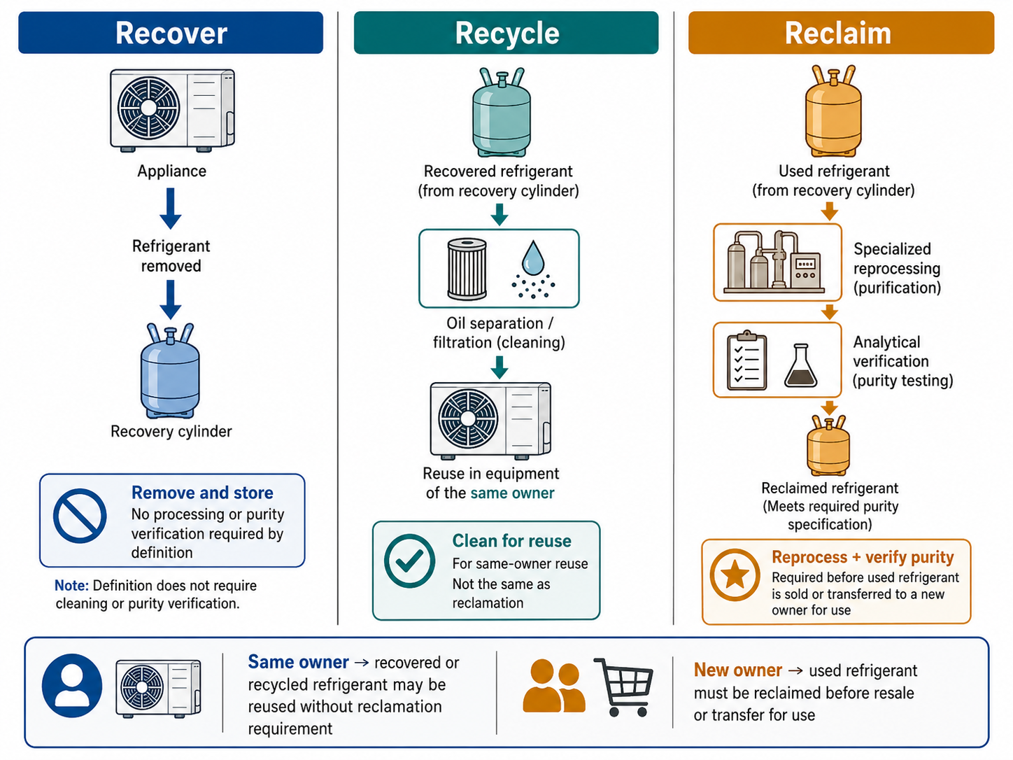
Figure 5.1.1 – Recover, recycle, and reclaim comparison.
AI-generated instructional figure: It may contain visual inaccuracies. Use the accompanying lesson text and cited authoritative sources to verify technical and regulatory details.
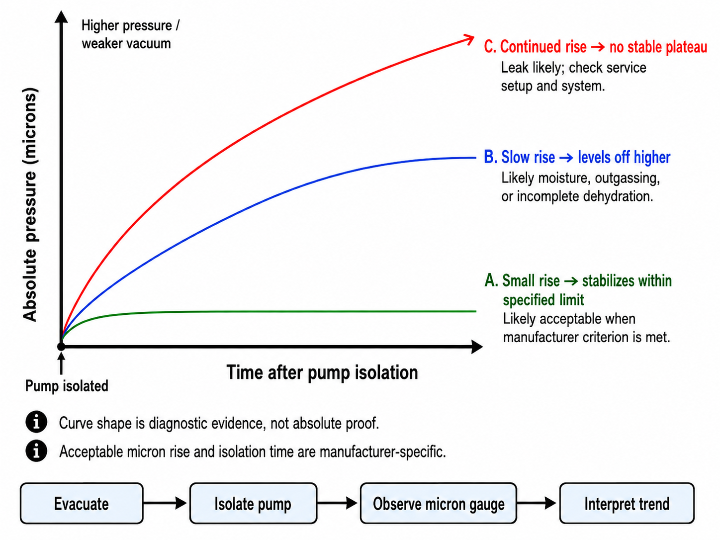
Figure 5.8.1 – Vacuum decay interpretation after the vacuum pump is isolated.
AI-generated instructional figure: It may contain visual inaccuracies. Use the accompanying lesson text and cited authoritative sources to verify technical and regulatory details.
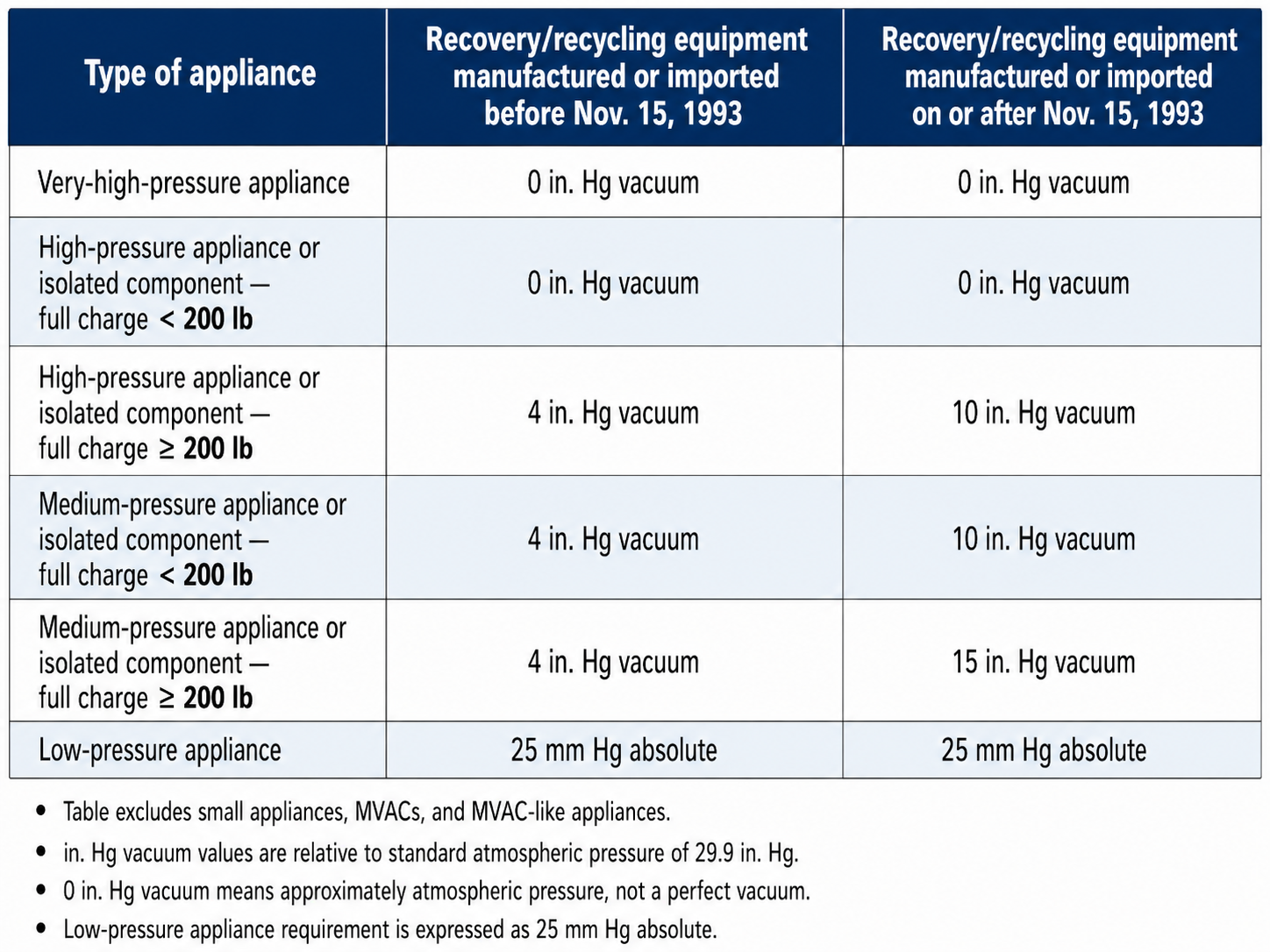
Figure 5.9.1 – Current Section 608 required evacuation levels for appliances other than small appliances, MVACs, and MVAC-like appliances.
AI-generated instructional figure: It may contain visual inaccuracies. Use the accompanying lesson text and cited authoritative sources to verify technical and regulatory details.
15. Detailed-Section Links
- Section 5.1 - Recover Recycle and Reclaim
- Section 5.2 - Recovery Equipment Categories
- Section 5.3 - Recovery Equipment Certification and Service Fittings
- Section 5.4 - Recovery Preparation
- Section 5.5 - Recovery Methods and Recovery Speed
- Section 5.6 - Recovery Cylinders
- Section 5.7 - Evacuation and Dehydration
- Section 5.8 - Standing Vacuum Test and Triple Evacuation
- Section 5.9 - Service-Practice Requirements and Exceptions